
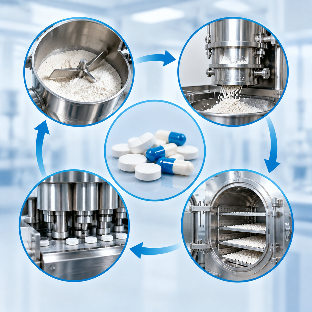
Solid-Dosage Process Mapping: Connecting Blending, Granulation, Drying, and Compression
Solid dosage process flow equipment mapping helps project teams connect unit operations, transfer points, utilities, controls, and documents before equipment is finalized. It is useful for process engineers, project managers, and pharmaceutical manufacturers planning a tablet or capsule line. SINOPED presents solid-dosage machinery, production-line integration, packaging systems, and engineering support as part of its public business scope, but each buyer should confirm requirements through its own quality, process, and regulatory owners.
Which process sequence should the equipment map follow?
The equipment map should follow the approved process sequence, not a generic equipment catalog. A typical solid-dosage route may include material preparation, weighing or dispensing, blending, granulation where applicable, drying, milling, final blending, compression or capsule filling, and packaging. However, the actual order depends on the formulation, process development decisions, containment needs, and the buyer’s approved manufacturing strategy.
A useful everyday analogy is planning a kitchen workflow for a complex meal. Buying a mixer, oven, and packaging containers is not enough. The team must know what is prepared first, what waits, what must stay covered, what needs cooling, and where cleaning happens. In the same way, solid dosage process flow equipment mapping connects each machine to the material state entering and leaving it.
For an overseas project team, the first decision is whether the product will be processed as a direct-compression blend, a wet-granulated material, a dry-granulated material, or another approved approach. That decision shapes whether the map includes a granulator, dryer, mill, binder preparation system, intermediate bulk containers, lifting equipment, sieving, or additional environmental controls. Buyers should confirm this sequence before discussing equipment layout, automation level, or packaging interfaces.
Where should transfer points be defined before equipment selection?
Transfer points should be defined wherever material changes equipment, container, height, room, exposure condition, or control responsibility. These points often create more project risk than the main machines because they affect dust release, segregation, cleaning access, operator handling, and line balance. A process map should show how material enters and exits each unit operation, not only the machine name.
| Transfer point | Common project decision | What buyers should confirm | Why it matters |
|---|---|---|---|
| Dispensing to blending | Manual charging, lifting, vacuum transfer, or contained charging | Material characteristics, exposure limits if applicable, weighing control, and room classification expectations | Poorly defined charging can create dust, operator burden, or batch reconciliation issues |
| Granulation to drying | Direct discharge, bin transfer, or trolley/container movement | Wet mass handling properties, hold-time expectations, cleaning access, and spill control | Material may be difficult to move consistently if moisture and texture are not considered |
| Drying to milling | Closed transfer, manual unloading, or integrated discharge | Target material condition, screen or mill interface, sampling access, and containment expectations | Inconsistent transfer can affect downstream particle-size preparation |
| Final blend to compression or capsule filling | IBC feed, hopper feed, force feeder connection, or capsule filler hopper connection | Segregation risk, feed height, refill method, and line stoppage behavior | Final blend uniformity may be affected by unnecessary handling or poor hopper design |
| Tablet or capsule output to packaging | Intermediate storage, dedusting, inspection, metal detection, and bulk handling | Product protection, inspection strategy, reject handling, and batch identification | Packaging readiness depends on controlled product flow and documentation |
These decisions should be recorded early because they affect equipment footprint, room layout, lifting devices, dust extraction, utilities, cleaning method, and operator movement. Requirements must be set by the buyer’s own quality and process owners.
How does granulation change the equipment plan?
Granulation changes the equipment plan by adding material transformation steps and additional interfaces. If the approved process uses wet granulation, the map commonly includes binder preparation or liquid addition, wet mass formation, transfer to drying, drying endpoint evidence, milling or sizing, and final blending. If the approved process does not require granulation, these machines may be unnecessary or may be replaced by direct blending and compression preparation.
This is why a sealed solid-dosage granulation line should be evaluated as a process arrangement, not only as a group of machines. SINOPED publicly presents a sealed solid-dosage granulation line at https://sinoped.com.cn/products/sealed-solid-dosage-granulation-line, but buyers should verify the current equipment scope, documents, interface drawings, and suitability against their own project requirements before reuse.
The key decision is whether granulation is part of the buyer’s approved product process. Equipment suppliers can help explain available configurations, but they should not replace formulation development, validation strategy, or internal quality decisions. Project teams should avoid assuming that a granulation route improves every powder blend. Some products may be suitable for direct compression, while others may require granulation for reasons determined during development. The map should reflect evidence from the buyer’s own process design, not a universal recipe.
Which misconceptions can distort solid dosage process flow equipment mapping?
Three misconceptions commonly lead to weak equipment maps. The first is that the process sequence is fixed for all tablets or capsules. The more accurate view is that sequence depends on formulation, material behavior, dosage form, and approved process design. A map should be product-specific enough to guide decisions, even when it uses standard unit-operation names.
The second misconception is that the largest machine defines the line. In practice, transfer points, intermediate storage, cleaning access, and packaging interfaces may decide whether the line functions smoothly. A tablet press or capsule filler cannot perform well in isolation if upstream feeding or downstream handling is unstable.
The third misconception is that automation removes the need for process ownership. Automation may support consistency, data capture, and operator guidance, but it does not decide acceptable process parameters, sampling strategy, or validation evidence. Those requirements should be defined by the buyer’s quality, engineering, and process teams. Equipment mapping should therefore show both physical flow and decision ownership.
| Misconception | More accurate view | Project risk if ignored |
|---|---|---|
| All solid-dosage lines follow the same sequence | The process sequence depends on the approved formulation and manufacturing route | Unnecessary equipment may be purchased, or required steps may be missed |
| Main machines are enough for planning | Interfaces, transfer points, and utilities are part of the operating line | Installation conflicts, material handling gaps, or layout rework may occur |
| Automation defines the process | Automation implements requirements set by process and quality owners | Controls may capture the wrong data or omit needed operator checks |
| Packaging can be planned later | Packaging flow affects inspection, batch handling, product protection, and line balance | Finished dosage forms may accumulate, wait, or move through poorly defined handoffs |
What documents should the team build before confirming equipment?
The team should build documents that connect process intent to equipment boundaries. A practical package typically includes a process flow diagram, material flow map, room and personnel flow concept, user requirement specification, equipment list, utility matrix, cleaning and changeover assumptions, control interface list, and preliminary layout. These documents do not replace validation or regulatory approval, but they give buyers and suppliers a shared basis for discussion.
A decision checklist can help keep the work evidence-bounded:
- Confirm the approved or intended manufacturing route: direct compression, wet granulation, dry granulation, capsule filling, or another defined approach.
- List each unit operation and describe the material state before and after it.
- Mark each transfer point, including charging, discharge, sampling, temporary storage, and reject handling.
- Identify cleaning boundaries, product-contact parts, access needs, and expected changeover considerations.
- Define utility expectations such as power, compressed air, vacuum, dust extraction, process air, chilled water, or other project-specific services where applicable.
- Record which requirements come from quality, which come from process development, and which come from engineering constraints.
- Confirm what documents the supplier will provide for human review, such as drawings, manuals, spare-parts information, and interface descriptions.
These steps help prevent the project from becoming a machine-by-machine purchase exercise. They also make it easier to identify open questions before procurement, factory acceptance activities, shipment planning, installation, and commissioning assistance.
How should packaging be connected to the solid-dosage process map?
Packaging should be connected as part of the process sequence, not treated as a separate afterthought. After compression or capsule filling, the product may pass through dedusting, inspection, metal detection where required by the buyer’s strategy, bulk holding, counting, blistering, bottling, cartoning, labeling, serialization-related interfaces where applicable, and case packing. The exact scope depends on market requirements, product presentation, and the buyer’s approved packaging design.
The main decision is whether packaging runs directly from production or through intermediate storage. Direct connection can reduce handling but may require stronger line balancing and coordinated stoppage logic. Intermediate storage may add flexibility but introduces additional identification, protection, and reconciliation considerations. Buyers should define how batches are separated, how rejects are controlled, and how packaging records connect to production records.
For project teams, packaging mapping also reveals practical facility questions: where operators load components, where printed materials are controlled, where finished goods leave the line, and how waste is removed. These points should be aligned with the buyer’s own documentation and quality expectations.
How can a project team map equipment around a solid-dosage manufacturing process?
Start with the product’s approved or intended manufacturing route, then list each unit operation in order. For every step, define input material, output material, transfer method, room location, operator action, cleaning boundary, utility need, and document owner. The result should be a process sequence map that connects machines, containers, controls, and packaging interfaces. It is not a production recipe and should be reviewed by the buyer’s process and quality teams.
What is the difference between a process flow diagram and an equipment layout?
A process flow diagram shows the order of unit operations and material movement. An equipment layout shows where machines, rooms, doors, utilities, and access zones are physically located. The process map should usually come first because layout decisions need to reflect material flow, transfer points, and cleaning needs. Both documents should be reconciled before equipment is finalized.
When should buyers involve equipment suppliers in process mapping?
Buyers commonly involve suppliers after the basic process route and user requirements are defined, but before final layout and interface decisions are locked. At that stage, suppliers can comment on equipment boundaries, transfer options, installation needs, and document packages. However, formulation decisions, quality requirements, and regulatory interpretations should remain with the buyer’s responsible owners and qualified advisers.
Can one equipment map be reused for multiple solid-dosage products?
One map may serve as a platform template when products share similar unit operations, containment expectations, and packaging routes. It should not be reused without review. Differences in powder behavior, granulation need, cleaning limits, tablet or capsule format, inspection strategy, and packaging components can change equipment interfaces. Buyers should confirm each product or product family against its own approved process design.
Share
Recommended Courses
Hydrogen Fuel Cell Reefer Truck

Semi Automatic KN95 Mask Making Machine
GMP Modular Clean Room System Manufacturer
Automatic Tablet Counting Machine
Recommended Solutions
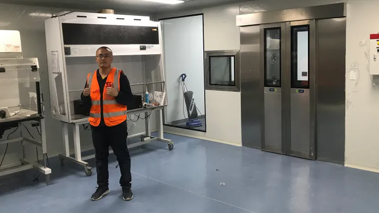
GMP Modular Cleanroom Solution for a Pharmaceutical Factory in the United States
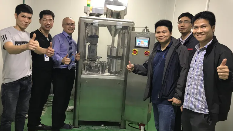
Automatic Capsule Filling Machine Project for Pharmaceutical Production in Vietnam

Softgel Encapsulation Machine Project for Pharmaceutical Laboratory Production in Iran